VW Vortex - Volkswagen Forum banner

How does Turn signals work on Mkv?

27K views 64 replies 5 participants last post by  GTI's  
#1 ·
Hi, im having issues with turn signals and are not used to "modern" car electronics.
Im used to owning a old 90's car for years which is easy to handle and work on.

The Mk5 Gti seems very different.

Just from googling im not sure if there is even a relay.
I also heard about modules that control electronics like blinkers etc instead so im quite confused how this work out.

Im actually trying to solve a problem with ONE blinker wont work.

And that is the Front right one, while all the others works.

Here is how far ive come:

Bulb's fine.
Connector for bulb is fine.
Harness for the entire healight also fine.

However, the blinker wire i can measure only 0.5volt max.
While other blinkers of course are doing their proper job, around 12volts.

I measured the blinker harness and the entire headlight harness and still cant get any higher readings.

Next i must figure if the problem are under the hood, or actually inside the car behind the firewall.


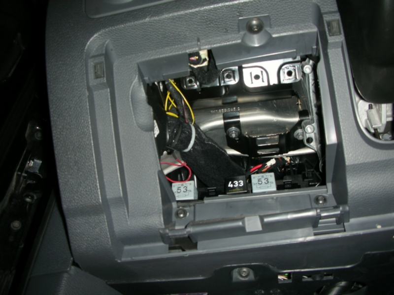
So i want to know, where and what does this wiring loom on the passenger side go to? (LHD CAR)
Where should i go next?


My plan was, if i could get proper readings from inside the car, behind the firewall, i could probably say the problem
was in the engine bay, which would save me time and be an easier job.


I just dont understand what is controlling these turn signals and where i find this unit.
 
#7 ·
Did check the location. Found a plate with some Relays. Could not figure out if one of these controlled the turn signal.
Will i have to take the entire unit out and find pin A-6 on the back side of it?
or is there any relays at front i could look at?
is it okay to unplug the unit or will it give error codes?
(i do not have vagcom)
 
#9 · (Edited)
As you may have figured out by now, the turn signals aren't controlled by relays on Mk5's.

I happen to have a German repair manual for the European-spec Mk5 Golf/GTI. But things like this are identical with the North American versions. As GTI's wrote, the right-side turn signal/blinker gets its power directly from the A/7 terminal (connector A, pin 7) at the J519 Central Electronics Control Module (CECM). The wire is black at the headlight, then black with green stripe back to the CECM.

The blinking is obviously controlled internally by the CECM. Again, no relay.

The turn signal stalk inputs directly to the CECM -- again, no relay there.

The CECM is above the driver's side pedals. You have to remove the panel with the violet OBD-II diagnostics connector above the pedals; the CECM connectors are at the mass of wires just above that.

The relay-type things you're seeing in that photo are right next to the CECM (in front of, as you're looking at them). At the bottom of the photo, you can see one of the Torx screws you have to remove to remove the panel to gain access to the CECM connectors.

Here's an image of the CECM connectors:


Note that this is for a U.S.-spec Jetta, so all the wiring may not be identical to yours. Also, this is from a DIY describing how to re-wire to install a European rear fog light (which we don't have standard in North America); so only the applicable B, C, and E connectors are labeled. I suspect the A connector is to the right of B.

The individual terminals are marked with tiny numbers molded into the connector. You may have to interpolate, since I believe they're only marked for the first and last terminals in each row.

Also be aware that, to remove any of the connectors, you first have to release the master lock -- that's the orange bar going across the entire panel, marked by the two white arrows. The lock slides a few mm to the left and clicks to unlock. Only then can you release the tabs to remove the individual connectors. Don't forget to re-engage the orange bar when you're done.
 
#11 · (Edited)
was blocked out of the forum for a few days, didnt realise until now that i had to reactivate my account.


As you may have figured out by now, the turn signals aren't controlled by relays on Mk5's.

I happen to have a German repair manual for the European-spec Mk5 Golf/GTI. But things like this are...........
Thanks alot for the throughout explanation!!! Super!

You said your bulb is fine, how did you test it? Did you use a DVM? I was able to replicate what I saw on your video with my DVM and VCDS. With a bad bulb in place or no bulb in socket volts went from below 1 to 11+ three to four times and then below 1 volt. That is the J519 module doing its job. With a good bulb in place the volts go from below 1 volt to 11+ volt as long as the turn signal is on and back below 1 volt when turned off.
Yes. I took the bulb from the other side (which are working) and tried it on the right side, still no result.
About the J519 cutting power, i found that on google, so nice to have it confirmed again, then i hopefully can exclude that thing from all this.

Was working in the engine bay yesterday trying to unwrap the main cable looking for any problems, which is couldnt find really.
Still measuring the exact same behaviour and results on the outside of the headlamp socket as i did inside the car on the J519.

However, there is a loose wire.. Really, it bothers me that i dont know where it belongs.

I took a picture.

The brown wire seem to split out into the same cable as the headlight connector, however it looks a bit longer than the connector itself.
if this has anything at all to do with the blinker, i dont know.


EDIT: I did have my car scanned a few weeks ago, not by vagcom (which im not able to get my hands on yet) but with a different very expensive and proffesional equipment.
I didnt write down the codes, but i might remember something like "Open circuit on turn signal" and a different code something like "terminal 30" thats all i remember.
Image
 
#10 ·
You said your bulb is fine, how did you test it? Did you use a DVM? I was able to replicate what I saw on your video with my DVM and VCDS. With a bad bulb in place or no bulb in socket volts went from below 1 to 11+ three to four times and then below 1 volt. That is the J519 module doing its job. With a good bulb in place the volts go from below 1 volt to 11+ volt as long as the turn signal is on and back below 1 volt when turned off.
 
#13 ·
that ground comes out of the same "tube" as the wires for the connector, doesnt look like it on the picture though.
Anyone knows where it goes, i would be happy to know.
I will try one more time to measure voltage over the bulb. if it just stays at under 1v, the problem could be inside the headlight.
if it keeps doing as every other place i measured, then im dead lost.
 
#17 · (Edited)
Well, on my 2009 GLI (wiring should be identical to your GTI), there are two wires coming out of the bundle that has all the headlight wiring, and that branch off to a two-pin connector between the headlight and the radiator -- see circle:


The thinner wire is brown with green stripe, and the thicker wire is solid brown (and therefore a ground).

I have no idea what those connect to; I can't see them looking through the grille from the front. My wiring diagrams don't show wires like those near the right-front headlight wiring, so finding what they are from the diagrams would be pretty tough...
 
#18 ·
I cannot get much more smarter on this issue.
I got a new montage video here.

I did however use battery grounding point when measuring, dont know if that matters.

but i could not get any readings on the turn signal socket.

download
[video]https://dl.dropbox.com/s/w7e8cws642jhfmr/My%20Video.avi[/video]

Or this to watch online:
https://www.dropbox.com/s/w7e8cws642jhfmr/My Video.avi
 
#19 ·
So it looks like you have power to headlight plug pin 9 black/green wire. Do you have continuity to ground at headlight plug pin 7? If that all checks out plug the headlight plug back in and now test the wiring at the back of the signal lamp socket. The back of the socket should have three wires, two brown ground wires together and the red wire for power. Test the back of the socket brown wires for continuity to ground, then test the red wire for power with key on signal swith on.
 
#20 · (Edited)
Test results:


Headlight connector pin 7 + battery ground = BEEP
Headlight connector (second ground wire) + battery ground = BEEP
Back of blinker socket ground + battery ground = BEEP
Also, blinker power wire + battery ground = BEEP (prob because bulb was in lol)

Blinker RED wire + battery ground = 0.01Volt (this with car running and blinker turned on)


Conclusion, Broken/burnt red wire inside healight? what do you think?
Never taken out a headlight and disasseble it on these cars before.
 
#21 ·
Sure looks like something is wrong in the headlight housing wiring. Does pin 9 on the plug and housing connector look Ok? As a final check you could connect the bulb to pin 9 and pin 7 at the plug. Remember that the module will kill power if it sees something amiss. So have it all hooked up before you turn signal switch on.
 
#22 ·
yes i was thinking the exact same thing. taking power straight from the black/green cable and route it directly to the bulb, and use ground already on socket.
i do wounder how it is wired up already inside.

does the black/green wire send all the power needed to the bulb, or is it just a "signal wire" which the bulb actually get its power from one of the thick power cables (yellow i guess)
 
#25 ·
This isnt very funny.
Now i got power straight from the green/black wire to the blinker bulb, and i have volts when the headlamp connector is not plugged,
but as i plug the connector, all drops back to 0.01volt again.

I did not cut the wire off, just getting power from it.

Maybe that wasnt a good idea in case there was a problem inside the headlight to begin with.
 
#26 ·
Ok. Now i routed the power cable directly into the blinker socket. And i cant get it to work. I have 0.01 volt in the socket, also the same behind the socket. However, if i remove the bulb and measure again i get 11.5 - 0volt repeatedly until it stalls. So with the bulb in which makes the circuit it wont work. What are the chances that it could be the ground? All the ground tests i did passed. This gets so depressing
 
#27 · (Edited)
Did you check pin 7 and pin 9 with a bulb? Here is a video clip of pin 7 and pin 9 at the plug being tested. This bulb was hooked up before turning ignition on and turn signal switch on.


Signal Lamp Video


Here is an video clip of pin 7 and pin 9 with a DVM. All hooked up before ignition and turn signal on. Power cycles a few time before the module does its job.


Signal DVM
 
#28 ·
Great. I gonna watch and reread that when u get internet working. Cannot load the videos on my phone. Thunder storm last night, had its consequences... Until then all i can mention is that the ground wire on the blinker goes from the blinker and to the parking light. Parking light working fine. Also tried to ground the bulb straight to the battery. Wanted to mention that i tried measure load over pin 10. The pin 10 reacts with turn signal. Alternate 0, 3 - 0,7v. When i turn off signal, pin10 also stops alternating.
 
#29 ·
I haven't been following this thread lately.

You guys have a wiring diagram? Would it help if you did? This is for a U.S.-spec 2005 Jetta GLI, but the wiring should be identical:


Doesn't look like Pin 10 (grey wire with red stripe) has anything to do with the turn signal. It's power for the parking lamp...

Turn signal power is Pin 9 (black wire with green stripe)...
 
#30 ·
That GTI has HID and uses a 12 pin plug not a 10 pin.


Pin 9 bk/green is power to turn signal and pin 7 brown is ground. He needs to test as above with a bulb or DVM. If all is good then the issue is with the housing pin connector or internal wiring or the socket for the signal lamp.
 
#31 · (Edited)
Ok got my internet back. Thanks for the headsup. I did these tests and have a 3 min throughout video about it.

its around 50mb.


Summary
There is no light on pin 7 and pin 9. Also there is no light using alternator as ground either.
Using a multimeter, i get alternating voltage until it stalls, when i add the test lamp to the circuit, multimeter show a total voltage drop to 0.00v.


What you also see in the video is that i have white tape wrapped around the (green/black wire) thats because i cut it off yesterday, right before the connector.
then i routed the green wire directly to the blinker lamp. I had exactly the same behaviour and nothing different: with a bulb in the socket i got 0.00v, with the bulb out, i had alternating voltage until it stalls.
So i soldered the green wire back to the connector.


i hope this video will clear up whats going on. Maybe it wasnt the headlight after all.
VIDEO:
https://www.dropbox.com/s/qyguehmdpoip2v3/Pin 9 Pin 7.avi?dl=0


EDIT: I will go out a bit later again and do the same test over the J519 unit with the test lamp. (if that makes sense?)
 
#33 ·
emergency flasher everything flashes but the front right (not flashing).

Also did a j519 test now, test lamp over black/green wire. It works, thank god.. Flashes, and stalls (stop flashing after about 3-4 flashes)

also did a recheck on the connector with the test lamp and still cant get any light.
 
#38 ·
Making a summary here so others can hang on to the issue.


Front Right blinker wont work at all. Not with hazard switch either.

Here is what i found out so far.


-Measuing behind bulb (on bulb socket) i get 0.00Volts.

-Taking out the bulb and measuring again gives me 12-0 volts alternating until j519 shuts off the power (stalls)
(which means, when there is no bulb in socket (no load) only multimeter)

-Tried swapping bulbs. The right bulb works fine on the left side.

-Socket looks fine. no corrosion.

-Unplug the headlamp connector and measure over pin 9 and pin 7 (blinker to ground)
Because the headlamp now is unplugged, i get voltage for a short time that stalls (j519 shuts off the power)

-I cut the black/green blinker wire right before the headlamp connector and routed it directly to the turn signal socket
(to assure that there is nothing going on inside the lamp) and i still get the same results. With no bulb,
i get voltage that stalls after 3-4 sec's, with bulb in, i get 0.00v

-I used a test lamp over the circuit in the headlamp connector and gets no light.

-I used a test lamp over the j519 to ground and it lights up, but stalls after 3-4 sec's and light goes dark.

-i measure over pin 10 (which i assume is park light/city light, and it somehow react when blinker is turned on,
goes from 0.3v-0.8v alternating. It probably shouldnt..


So summary,
The J519 unit seems to do its job, test lamp lights up over the unit, but it goes dark after a few seconds.
I guess thats how the j519 is supposed to work when there is something wrong.

a scan shows, "open circuit" for turn signal.

measuring the blinker socket wont light the test lamp at all or the multimeter.


IF the bulb IS removed from the circuit, and i try measure again with multimeter, i will get alternating 12-0v until it stalls 3-4 sec's.

However, the test lamp wont light.

I tried using different ground points, like alternator and chassis, still no light on test lamp. But multimeter would though.
I guess the multimeter has barely any resistance at all.
 
#41 ·
well the pin 10 is also dead now.

at the moment i switch ignition on and the lights light up, the right park light wont work, measuing 0.30v, after 3-4 seconds its goes out to 0.00v
exactly the same issue here as with the turn signal now.

I cannot guess anything but cracked, damaged wires in the wiring from the firewall somewhere to the headlight, maybe causing a short or interfering with each other. mainly pin 9 and pin 10, since other lights seem to work.
just a guess..

i wish i could start unwraping the cloth tape and have a look, but the fog light is also connected, and i cant reach for the connector.
Probably must go beneath the car, remove the covers and take it off from there which i am unable to do.

Got a picture here.

Image