

OK, this thread was initiated, because of this thread... http://forums.vwvortex.com/zer...71900
As stated, I decided to rebuild and add (easy) adjustability to the cold control pressure. This wasn't my design, I got it from here: http://www.pelicanparts.com/te...g.htm
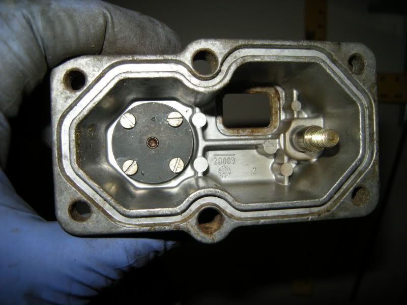
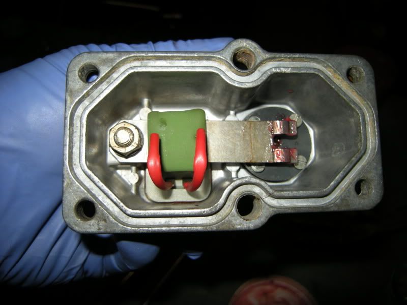
1st step, remove the screws and be careful when removing the bottom cover. It's under spring tension. This is what you'll be looking at. The spring, hat and pin have been removed, exposing the entire heating element. I've had heating elements that read 12 ohms and were fine. IIRC, Bentley call for 16-22ohms? As long as you're not open, I'd use it.
![Image]()
Remove the horseshoe clip holding the electrical connection, then the 10mm nut and washers. The threaded stud/plug (to the right) sets "Cold Control Pressure". The blackish cylinder (to the left) houses a diaphragm that controls both "Cold & Warm Control Pressure".
![Image]()
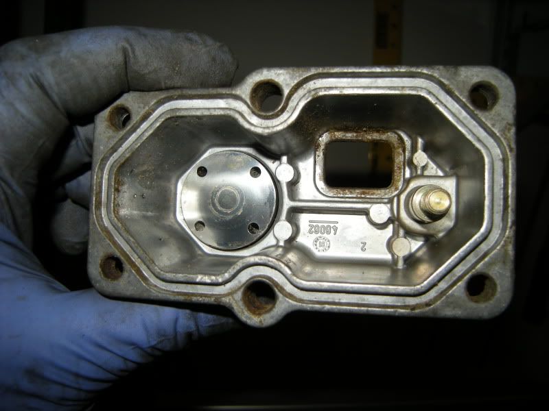
I removed the 4 screws while the cylinder was still in the housing. I got ahead of myself and should have pressed it out (don't hammer) first, with a vice or press, then removed the screws.
Once the lower cover is off remove the steel diaphragm. If it's sticking, loosen it with carb cleaner and compressed air. Like a jackass I scratched my diaphragm, because it was stuck and I picked at it with a small screwdriver. It wasn't a fatal scratch, so all is good. This diaphragm is thinner than a piece of paper, so be careful.
![Image]()
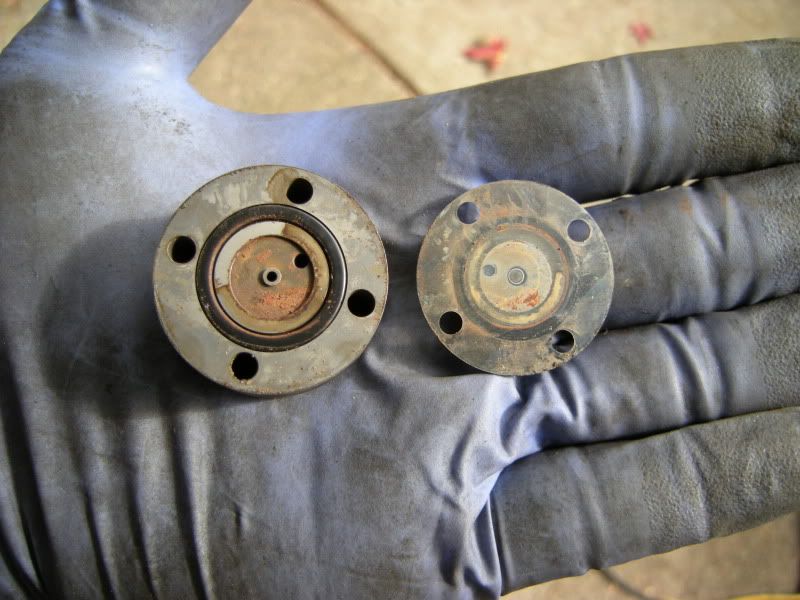
Here's the o-ring and rust that was under the diaphragm.
![Image]()
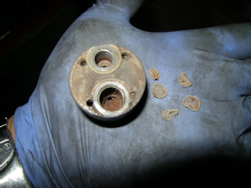
I mentioned I sprayed carb cleaner at the supposedly clean looking screens, and blew it out with compressed air. I couldn't blow air through it with my mouth, so I pulled the 5 screens. and a lot more rust was hiding under them. Air went through, effortlessly.
![Image]()
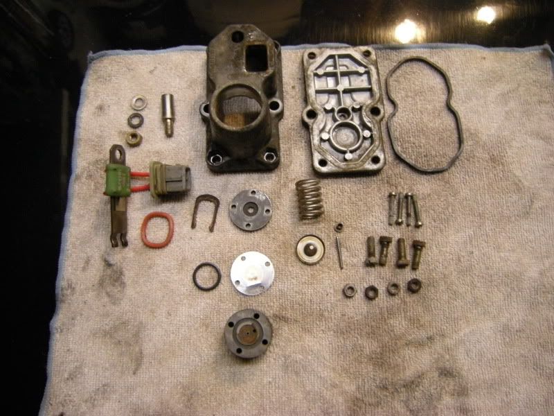
Prior to cleaning parts. Don't look at the scratched diaphragm.
![Image]()
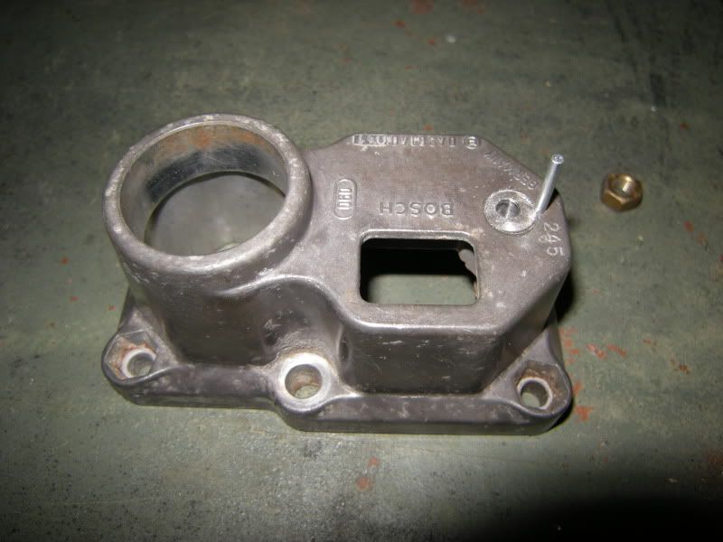
Reinstall the plug, flush with the top housing using a little antisieze. Use a drill press and drill the 1.5mm roll/tension pin hole first, then tap the pin in. Next, centerpunch, drill then tap the hole for the 5mm bolt. If you're not 100% centered, that's fine.... get it as close as humanly possible.
A roll pin assortment is available in a small Dorman blisterpack for about $3, in the "Help" isle of auto stores. There's only (1) 1.5mm pin in it. In my pic, I used the next size up, as I've made these in the past. Just tap it until it just peeks through the bottom, then cut and file off the excess.
![Image]()
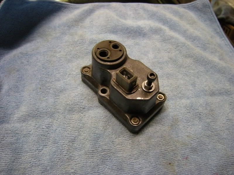
Start reassembly; anything that had grease was regreased with synthetic. For the "cold" plug, tap the plug about 2-3mm deeper than it originally was. Press the blackish cylinder back in (using a little antisieze), leaving it 1-2mm higher than it originally was. Large port is to the right when "in position".
![Image]()
Bottom out bolt with washer and nut and you're done.
![Image]()
Setting pressures...
Reinstall fuel lines, but keep the plug disconnected and don't bolt the CPR to the block. At this point, have the CIS gauge hooked up. Pull the injectors, jump the FP relay and set the sensor plate height. Reinstall the injectors, and start the car. Remember that lower control pressure is richer.
Now if you tapped the plug lower than it was, the cold control pressure should be very low. Turn the nut clockwise, so it's pulling the plug out. 20-25 psi is what I aim for, depending on ambient temperature. Mine was set to 21 psi @ about 55*F.
If the pressure is higher than your goal, tap the plug in. Make sure the nut isn't bottomed out, place the CPR on something solid and give it a whack. I use the intake manifold for stability and start with light blows. While watching the gauge, you'll get a feel with how much force to use and this plug requires some.
Once the pressure is within spec, plug the CPR in. Your harness should have a steady 12v. I waited until the fan ran twice, but didn't need to. After a minute, the pressure will have crept as high as it will, as it's working off the internal heating element. Mine pegged at 40 psi. Now, what a lot of people don't know, is that the "warm" pressure is also adjustable. I stumbled upon this in a MB forum.
Since you left the cylinder higher, your warm control pressure should be lower (richer) than ideal. Using a flat tipped drift, tap the cylinder down. Do not tap the banjos, and do not use a lot of force. I've damaged a cylinder (in the past) and this plug doesn't require a lot of movement for significant changes.
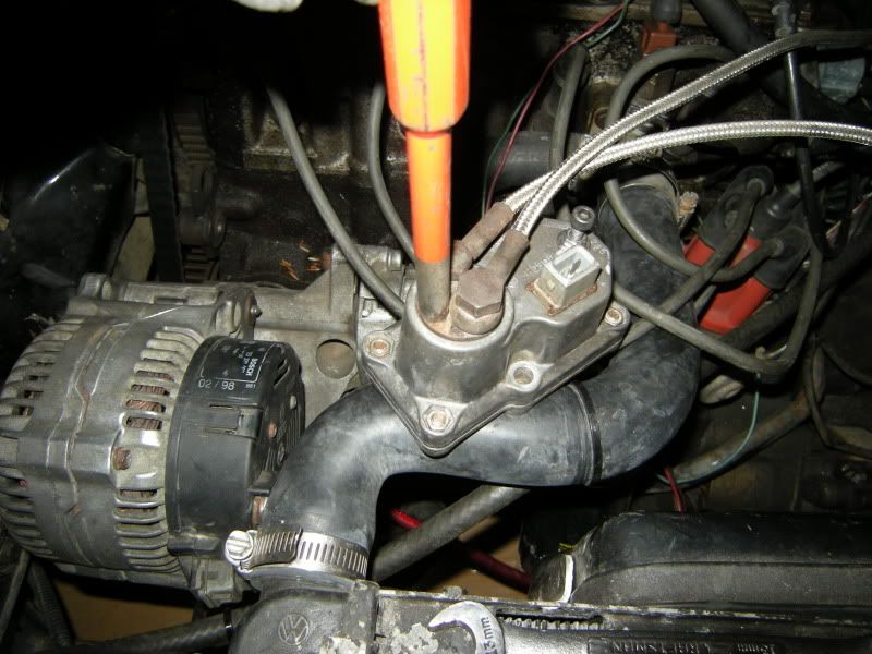
This is the only safe place to tap the cylinder.....
![Image]()
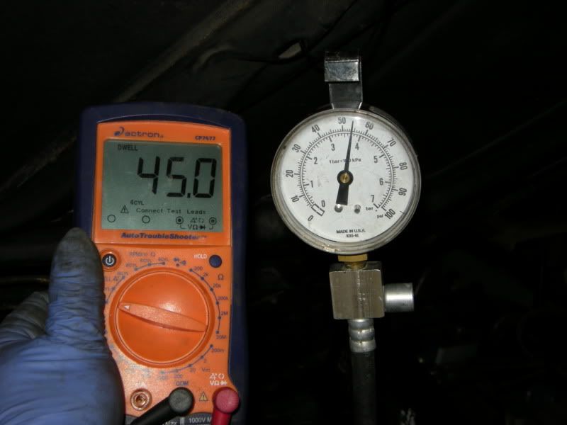
.... to get this.
![Image]()
Originally, I accidentally overtapped to 60 psi, disassembled, reassembled, then set it to 54 psi. Because of this, I wanted to verify my cold setting, and saw 40 psi. My point being, if you reopen it, reverify both settings. I've verified both settings 3 times since hooking this up.
I ended up resetting my warm pressure to 52 psi. The range you want to be in is 49-55 psi, so I wanted to be in the middle. For a modified engine, I'd want to be at 49 psi or lower. All of this disassembly has me thinking of making a version "2" with easier cold and adjustable warm settings.
In the end, I saw 21 psi cold, 52 psi warm with a 45* dwell +/- .2* @ 900rpm. My cold idle sucks, because I need to address my auxiliary air valve. I'm only really concerned about warm idle anyhow.
-Todd
As stated, I decided to rebuild and add (easy) adjustability to the cold control pressure. This wasn't my design, I got it from here: http://www.pelicanparts.com/te...g.htm
1st step, remove the screws and be careful when removing the bottom cover. It's under spring tension. This is what you'll be looking at. The spring, hat and pin have been removed, exposing the entire heating element. I've had heating elements that read 12 ohms and were fine. IIRC, Bentley call for 16-22ohms? As long as you're not open, I'd use it.

Remove the horseshoe clip holding the electrical connection, then the 10mm nut and washers. The threaded stud/plug (to the right) sets "Cold Control Pressure". The blackish cylinder (to the left) houses a diaphragm that controls both "Cold & Warm Control Pressure".
I removed the 4 screws while the cylinder was still in the housing. I got ahead of myself and should have pressed it out (don't hammer) first, with a vice or press, then removed the screws.
Once the lower cover is off remove the steel diaphragm. If it's sticking, loosen it with carb cleaner and compressed air. Like a jackass I scratched my diaphragm, because it was stuck and I picked at it with a small screwdriver. It wasn't a fatal scratch, so all is good. This diaphragm is thinner than a piece of paper, so be careful.
Here's the o-ring and rust that was under the diaphragm.
I mentioned I sprayed carb cleaner at the supposedly clean looking screens, and blew it out with compressed air. I couldn't blow air through it with my mouth, so I pulled the 5 screens. and a lot more rust was hiding under them. Air went through, effortlessly.
Prior to cleaning parts. Don't look at the scratched diaphragm.
Reinstall the plug, flush with the top housing using a little antisieze. Use a drill press and drill the 1.5mm roll/tension pin hole first, then tap the pin in. Next, centerpunch, drill then tap the hole for the 5mm bolt. If you're not 100% centered, that's fine.... get it as close as humanly possible.
A roll pin assortment is available in a small Dorman blisterpack for about $3, in the "Help" isle of auto stores. There's only (1) 1.5mm pin in it. In my pic, I used the next size up, as I've made these in the past. Just tap it until it just peeks through the bottom, then cut and file off the excess.
Start reassembly; anything that had grease was regreased with synthetic. For the "cold" plug, tap the plug about 2-3mm deeper than it originally was. Press the blackish cylinder back in (using a little antisieze), leaving it 1-2mm higher than it originally was. Large port is to the right when "in position".
Bottom out bolt with washer and nut and you're done.
Setting pressures...
Reinstall fuel lines, but keep the plug disconnected and don't bolt the CPR to the block. At this point, have the CIS gauge hooked up. Pull the injectors, jump the FP relay and set the sensor plate height. Reinstall the injectors, and start the car. Remember that lower control pressure is richer.
Now if you tapped the plug lower than it was, the cold control pressure should be very low. Turn the nut clockwise, so it's pulling the plug out. 20-25 psi is what I aim for, depending on ambient temperature. Mine was set to 21 psi @ about 55*F.
If the pressure is higher than your goal, tap the plug in. Make sure the nut isn't bottomed out, place the CPR on something solid and give it a whack. I use the intake manifold for stability and start with light blows. While watching the gauge, you'll get a feel with how much force to use and this plug requires some.
Once the pressure is within spec, plug the CPR in. Your harness should have a steady 12v. I waited until the fan ran twice, but didn't need to. After a minute, the pressure will have crept as high as it will, as it's working off the internal heating element. Mine pegged at 40 psi. Now, what a lot of people don't know, is that the "warm" pressure is also adjustable. I stumbled upon this in a MB forum.
Since you left the cylinder higher, your warm control pressure should be lower (richer) than ideal. Using a flat tipped drift, tap the cylinder down. Do not tap the banjos, and do not use a lot of force. I've damaged a cylinder (in the past) and this plug doesn't require a lot of movement for significant changes.
This is the only safe place to tap the cylinder.....
.... to get this.
Originally, I accidentally overtapped to 60 psi, disassembled, reassembled, then set it to 54 psi. Because of this, I wanted to verify my cold setting, and saw 40 psi. My point being, if you reopen it, reverify both settings. I've verified both settings 3 times since hooking this up.
I ended up resetting my warm pressure to 52 psi. The range you want to be in is 49-55 psi, so I wanted to be in the middle. For a modified engine, I'd want to be at 49 psi or lower. All of this disassembly has me thinking of making a version "2" with easier cold and adjustable warm settings.
In the end, I saw 21 psi cold, 52 psi warm with a 45* dwell +/- .2* @ 900rpm. My cold idle sucks, because I need to address my auxiliary air valve. I'm only really concerned about warm idle anyhow.
-Todd


 opcorn:


